

Remote Communication System

KLfiber used by U.S. Navy, U.S. Coastguard, NOAA, and Cruise ships


The KLfiber systems offer over 400 configurations and 6 primary applications, providing users the ability to select their individual operational needs.
These systems provide the user the option of selecting five primary links:
- Television Receive Only (TVRO)
- Very Small Aperture Terminal (VSAT) transmit and receive
- Global Position Satellite (GPS) fiber optic link
- Search and Rescue (SAR)
- non-powered Multiplexer/Demultiplexer (MUX/DEMUX)
Once installed and optimized for individual installations, the KLfiber systems require no operator intervention.

KLfiber System Configuration Chart

System Design Criteria
The KLfiber system designs have evolved and resulted from years of user experiences. They incorporate cost effectiveness in system configurations. They provide either: military qualified or commercial equivalence of components; military qualified or commercial equivalence of physical interfaces. They incorporate flexibility in M&C configurations. Serial RS-232 or RS-422 is the standard M&C implemented. Standard Ethernet, Ethernet over Copper (EoC) or wireless M&C channels are also available upon request.
The fiber link criteria is always critical and as such, KLfiber system designs incorporate the fiber link margins required in setting up pre-installed systems. As an example, a 1600 foot trunk between the remote and central unit results in an approximate insertion loss of 6.00dB. KLfiber L-band system assemblies provide a nominal dynamic range of approximately 12.1dB providing a link margin of approximately 6.10dB. KLfiber M&C assemblies provide a nominal dynamic range of approximately 16.00dB providing a link margin of 9.80dB. Factory pre-sets are incorporated into the fiber converter assemblies (FCA) to optimize the operability of the fiber link to support the link margins.
Electromagnetic and Radio Frequency immunity are corner stones of all KLfiber system designs. Lightening surge protection is also provided on all coaxial L-band channels and, when implemented, EoC channels.
Mean Time Between Failure (MTBF) of parts and components integrated into the KLfiber systems are a key factor of their design. Currently, the KLfiber systems have a calculated MTBF of >51,000 hours (5.82Years)
System Implementation
TVRO (Television Receive Only)
The implementation of KLxT systems requires that the user definitions of the broadcast system provide: the TVRO broadcast channel definitions, i.e., C-Band, KuLO, KuHI bands, linear, or circular; the required number of broadcast channels; and space available within the user’s antenna and within the broadcast space.
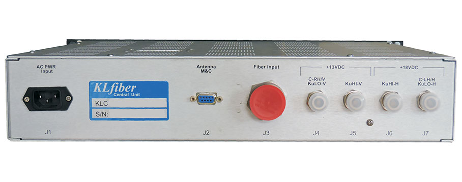
The KLfiber TVRO KLCT Central Units provide the user the ability to provide their broadcast equipment the necessary Integrated Receiver-Decoder (IRD) bias voltage of +13VDC/+18VDC or none if not required.
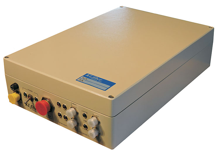
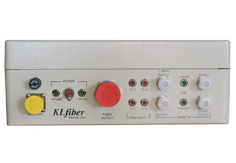
The KLRT Remote Units have been designed and configured to provide the antenna Low Noise Block-converter (LNB) the necessary bias voltage to coincide with the required broadcast channel polarization.
VSAT (Very Small Aperture Terminal)
The implementation of KLxV systems requires that the user definitions of the broadcast system provide: the VSAT broadcast channel definitions, the M&C necessary for operations; and space available within the user’s antenna and within the broadcast space.
GPS (Global Position Satellite)
Implementation of the KLxG systems require very little user definitions as the interfaces are limited to: the conversion of GPS L1/L2 L-band from the AE to the GPS receiver; the C&C interface between the GPS receiver to and from the AE; and the fiber FCA M&C between the KLW8RG and the KLCW8G.
SAR (Search and Rescue)
Implementation of the KLxS systems also requires very little user definitions as the interfaces are limited to: L-band or S-Band conversion (1544.4MHz or 2226MHz respectively) from the antenna group to the SAR receiver baseband equipment; and the fiber FCA Serial M&C between the KLCS Central Unit and the KLCS Remote Unit.
MUX/DEMUX (Non-Powered Multiplexer and Demultiplexer)
Implementation of MUX/DEMUX is dependent solely upon user fiber trunk utilization. These units have been designed to support 4:1, 8:1 and 16:1 functionality. They are totally non-powered units which were designed to provide multiplexing of multiple fiber nodes onto a single fiber trunk, thereby reducing costly multi-core cable requirements to a minimum.
The functionality of the MUX/DEMUX has been implemented with a simple Coarse Wave Division Multiplex (CWDM) scheme. This functionality has also been integrated into many of the KLfiber fiber transmission systems whenever minimizing the trunks are required or desired.